> For the complete documentation index, see [llms.txt](https://hkust-robotics-team.gitbook.io/hkust-robotics-team-software-tutorial/llms.txt). Markdown versions of documentation pages are available by appending `.md` to page URLs; this page is available as [Markdown](https://hkust-robotics-team.gitbook.io/hkust-robotics-team-software-tutorial/advanced-notes/introduction-to-embedded-system-stm32.md).
# Introduction to Embedded System - STM32
Introduction to fundamental concepts and knowledge of STM, Interrupt, GPIO, and Timer.
Authors
Henry Loi
## Table of Content
[#before-start](#before-start "mention")
## Before Start
### What is Embedded system?
An embedded system is a system in which the computer (generally a microcontroller or microprocessor) is included as an integral part of the system. For example, your phone, ATM, door ball, etc.
### What is STM32?
STM stands for STMicroelectronics, a multinational corporation and technology company. It is famous by its microcontroller integrated circuits. In daily life, STM mainly stands for STM microcontroller unit series.
### What is Microcontroller (MCU)?
An MCU is an intelligent semiconductor IC that consists of a processor unit, memory modules, communication interfaces, and peripherals. In short, a lower-level CPU.
We mainly use STM32 Series MCU for our embedded system development.
Here is the list of STM32 Series MCU:
Figure 1: STM32 Series Table
The MPU naming logic of STM is similar to CPU.
**Intel STM**\
 **VS** 
## Interrupt & Polling
### What is polling?
Let’s try to understand the concept first. You have many things to do in your everyday life Consider your daily life as a while loop like this:
```c
while(everyday){
wakeup;
breakfast;
lunch;
tea;
dinner;
supper;
sleep;
}
```
> Everyone of you has a mobile phone, will you do a polling on your mobile phone ? :mobile\_phone:
>
> How do you know if someone calls you ? :calling:
>
> What happen if your mobile phone is set to mute ? :no\_bell:
Here is a polling code example:
```c
int main(){
HAL_Init();
SystemClock_Config();
MX_GPIO_Init();
while (1){
if (HAL_GPIO_ReadPin(GPIOB, GPIO_PINC) == 0){
// follow sequence to toggle the RGB LED
}
}
}
```
### What is Interrupt?
You can consider interrupt is a procedure call. If you enabled the interrupt, the machine will go to do that procedure. That procedure is called **Interrupt Service Routine (ISR)**.
Note that once you enabled the interrupt, you **DON’T** need to do polling. If you use both polling and interrupt for the same event, you have a major conceptual error
> Do you need to continuously keep checking your phone to see if someone calls you if you set your phone to ring mode ? :thinking:
In STM32, there is a NVIC (Nested Vectored Interrupt Controller) to control up to 81 interrupts and with 16 level of priority.
### How to enable interrupt?
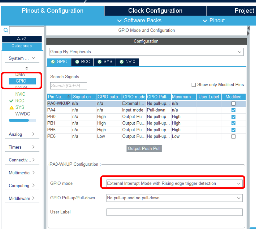
In CubeIDE, before you generate the code, you need to enable the GPIO to be interrupt. Let say we use PA0 as an example:
1\. Select GPIO\_EXI0 in .ioc
2. GPIO mode -> External Interrupt Mode with Rising edge trigger detection
3. In NVIC, Enable the EXTI line0 interrupt.
4. In Code generation, EXTI line0 interrupt, check the box Call HAL handler. You can then generate your code.
5. Originally, the implementation of ISR are contained in the file `stm32f10x_it.c`. Open the file and locate the following:
```c
/**
* @brief This function handles EXTI line0 interrupt.
*/
void EXTI0_IRQHandler(void){
/* USER CODE BEGIN EXTI0_IRQn 0 */
/* USER CODE END EXTI0_IRQn 0 */
HAL_GPIO_EXTI_IRQHandler(GPIO_PIN_0); // <- HAL ISR
/* USER CODE BEGIN EXTI0_IRQn 1 */
/* USER CODE END EXTI0_IRQn 1 */
}
```
6. We can modify the code and replace the replac the orginal IRQHandler:
```c
void EXTI0_IRQHandler(void) {
/* USER CODE BEGIN EXTI0_IRQn 0 */
if (__HAL_GPIO_EXTI_GET_IT(GPIO_PIN_0) != RESET){
__HAL_GPIO_EXTI_CLEAR_IT(GPIO_PIN_0);
HAL_GPIO_EXTI_Callback(GPIO_PIN_0);
}
/* USER CODE END EXTI0_IRQn 0 */
// HAL_GPIO_EXTI_IRQHandler(GPIO_PIN_0); // this line is commented
/* USER CODE BEGIN EXTI0_IRQn 1 */
/* USER CODE END EXTI0_IRQn 1 */
}
```
## GPIO
We have already taught what is GPIO before, however, we would like to go one step further to explain the difference between different GPIO ouput mode and why it is programmable.
Let's review the previous gpio notes: [GPIO](/hkust-robotics-team-software-tutorial/tutorial/tutorial-2-basic-io/gpio-1.md)
## Timer
Same as GPIO, we have taught PWM timer before, but we didn't explain the concept in detail.
> What do **CCR** actually means?
>
> Is combination of **prescalar (PSC)** and **auto-reload (ARR)** really a up-to-you combination?
>
> When do we need +1 when calculating **prescalar (PSC)** and **auto-reload (ARR)**?
Let's review the previous PWM notes: [PWM and Servo motor](/hkust-robotics-team-software-tutorial/tutorial/tutorial-3-advanced-io/pwm.md)
## Communication Protocol
Hartin's TODO