CAN and Robomaster Motor
What is CAN?
CAN, or Controller area network, is an electronic communication bus defined by the ISO 11898 standards. Those standards define how communication happens, how wiring is configured and how messages are constructed, among other things. Collectively, this system is referred to as a CAN bus.
All nodes can “hear” all transmissions. There is no way to send a message to just a specific node.The CAN hardware, however, provides local filtering so that each node may react only on the interesting messages.
Principle of CAN
Differential Signal 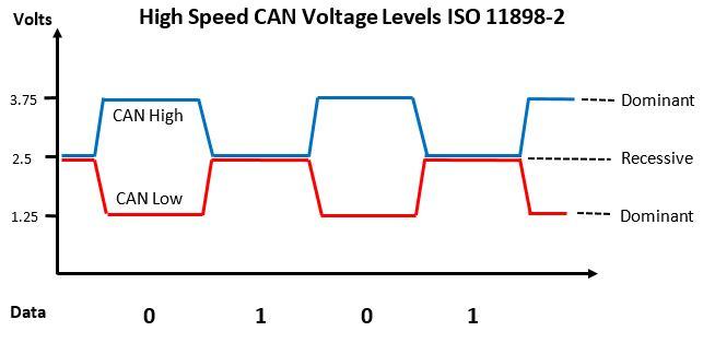
The way data is sent on the CAN Bus is through differential signalling. We use both the line CAN high and CAN low to transmit the data at the same time. Compared to something like UART, CAN is more reliable and less susceptible to interference/noise.
Recessive level - represent logical 1
Dominant level - represent logical 0
There are four types of CAN frames:
Data Frame
Remote Frame
Error Frame
Overload Frame
Data frame
Base frame format (11-bit identifier) 
Extended frame format (29-bit identifier) 
A CAN data frame can be divided into 8 parts:
Start of frame (SOF)
arbitration (consists of 2 parts) - CAN-ID: 11- or 29-bit identifier - a remote transmission (RTR) bit.
control
data
cyclical redundancy check (CRC)
acknowledge (ACK)
end of frame (EOF).
Normally, we will only focusing on three parts: CAN-ID, Control and Data.
CAN ID: a unique ID that identifies the devices connected to the bus (used to send/receive data from specific targets)
Control: Inform the length of data in bytes (0-8).
Data: Containing actual data value, e.g. current for motor.
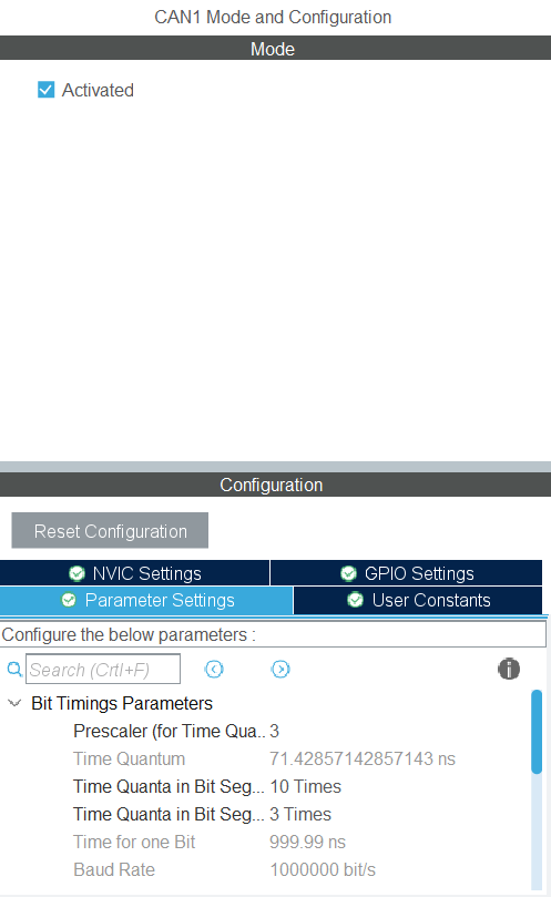
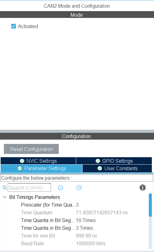
STM32 CAN config
This should already be done for you in our boilerplate code.
CAN1(master)
and CAN2(slave)
Clock Config
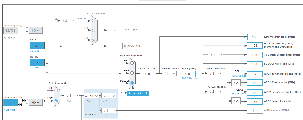
Just make sure the clock config are the same.
CAN functions
Before trying to use CAN, please download this zip file and place the can.h and can.c in the Inc and Src folders respectively. We have defined some helper functions for you to make your life easier.
Initialization
As mentioned, there are 2 CAN buses available to you on the mainboard. The hcan1 and hcan2 objects are defined by the STM32HAL library.
We have created a can_init() function to help you initialize the buses. Please make sure you call this function once before your while loop (like all your other initialization functions).
After initialization, please also make sure to call the function below repeatedly inside your while loop to ensure you are able to continuously send data to the motors and receive feedback:
Sending CAN message
If you want to drive a motor, you can use the following function:
The Motor type is an enum we have defined for you that looks like this:
The maximum number of C620 Robomaster motors that can be used on a single CAN bus is 8, hence the limit. (RDC participants don't have access to that many motors tho) The motor number corresponds to the CAN ID of the motor, which is configured on the motor itself. More on configuring that later.
Retrieving CAN message
To help you receive feedback from the motor, we have defined the following struct for you that contains everything you can get from the motor:
To actually retrieve the data from a specific motor, you can use this function below:
Example code
The code below shows you how to retrieve and send CAN message at the same time. This will rotate your motor in clockwise.
The example above assumes you are using CAN1, and that your motor has a CAN ID of 0 (NOT 1).
Robomaster Motor
The Robomaster Motor (commonly shortened to RM in our team), pictured below, is the motor you will be using in the RDC:

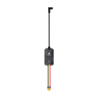
Aside from the motor itself, we also need an external device to convert the CAN signals we send into commands the motor actually understands, called an RM-ESC (Electronic Speed Controller), pictured below:
Wiring and power supply
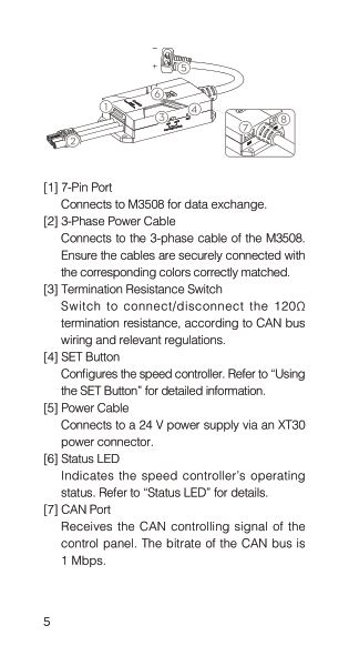
Both [1] and [2] will attached to the RM motor.
Connect [5] to a 24V cell battery (ask hardware for help if unsure!)
[7] is CAN port and [8] is PWM port
should only choose 1 port to use
We talk about why you might want to use CAN over PWM at the bottom of this doc
Potential Damage
Collision
Dropping
Somehow your robot has the RM motor or ESC exposed to external objects and your robot crashed into them
Overheating
Cause
Overdriving (Forcing the motor to provide excessive amount of torque)
Short circuit
24V power wire is shorted and so the motor is provided with too much current
Heating effect (Hopefully you have learnt high school physics)
Results
Non Permanent Damage
Just some warmth
Permanent Damage
Electrical component gets damaged
More serious cases: Sparks and Smoke
Note
Please check the temperature of both ESC and RM motor if something weird happened. e.g. burning smell, motor didn't move when it previously worked properly
Prevention
Make sure that the ESC is tightly tied to the robot internally
Ensure there is nothing that blocks the rotation motion of the RM motor (E.g. Loose screws)
Turn off the 24V power supply
Remove the obstacle if you can or else find a mech member to deal with it
Overheating
Irritating Smell (Smells like burning rice lol)
Cool down in whatever way you can (Preferably use compressed air in the lab to cool it down)
Always turn off 24V power supply first when accidents happen
Configuration of RM ID
Steps:
Find a hard rod with a small end (We use tweezers most of the time)
Poke the SET Button[4] in the upper image to set the CAN ID
Number of times to press the SET Button = CAN ID + 1
The first press is to tell the RM ESC to enter CAN ID configuration mode
Watch the LED blink and make sure the CAN ID is correct
ID = LED blink time - 1
Calibration of the RM motor
Background
RM motors can only be controlled when the ESC knows the condition of the motor. (E.g. Current and inductance) Even though the RM motor is a commercialized product, it is extremely difficult for every single motors to be identical. Thus, we need to let the ESC to know the actual condition of the RM motor through calibration.
Procedures
Again, find a hard rod with a small end
Press the SET Button for a long time and it will enter the calibration mode
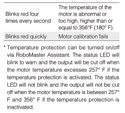
Wait until the LED blinks green quickly.
The motor will start spinning but no worries, just wait until it stops.
Please ensure that there is no obstacle bothering the RM motor spinning motion.
What does the LED signal mean?
TLDR: Any LED signal except for a green blinking LED is not a good sign. 

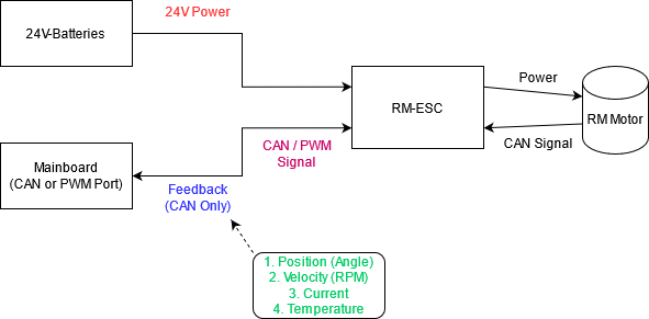
Electrical Structure of a RM control system
Common Errors
Arranged in order of occurrence
24V power
No LED Light at all
No input power source
1. Check if the wire is plugged in or not 2. Check if the fuse is burnt 3. Ask hardware people for help
Solid red LED
No CAN signal from the RM Motor
Check the 7-pin wire connected to the RM Motor
Red LED blinking twice
The 3-phase cable is not connected.
Check the connection between RM-Motor and ESC (3-phase cable)
Signal
Do these when you are sure it's not the power's problem CAN:
Wrong CAN ID
Check Check Check
Reinitialize the correct CAN ID
Wrong CAN Bus
See if any motors are not moving the way you want
Send message to the right bus instead
Wrong CAN Port
Again, Check Check Check
I mean, just don't plug it into the wrong hole
PWM:
Incorrect frequency/ on time initialized in the code
1. Check with Oscilloscope 2. Check your code
Change it back lol
False soldering for the pwm pins on the mainboard
Find a hardware member for help
Hardware member should deal with it
Broken ESC (Basically never happened)
When you are a 100% sure you did everything correctly and the motor is not working properly Swap with an ESC that works and see if it's actually faulty
Just get a new ESC
CAN vs PWM
Both PWM and CAN can be used to control the motor.
PWM:
Advantage:
Easier to use and implement
Disadvantage:
PWM can only output signal and can't get the feedback data back. As in real-life condition, the motor cannot be exactly identical (As said from above). If we just output a signal without getting feedback, the speed of motor may not be the same. Therefore, the wheelbase may not move as you want it to be.
CAN:
Advantage:
FEEDBACK FROM MOTOR!! Feedback is important because while we can command the motor to do something (e.g. move at a certain speed), there's no guarantee the motor actually does that perfectly. Manufacturing errors exist, and fluctuations happen. A motor you command to move at 100rpm may actually be moving at 90rpm or 120rpm. For maximum accuracy and precision, we want to monitor the actual state of the motor, and use the feedback to implement something we call closed loop control. (See: PID)
Disadvantage:
A bit annoying to implement(requires more work)
Hard to debug when there are problems
Could be because of:
CAN IC
CAN wire
Hardware soldering
CAN port
Code
or EVERYTHING
Driving RM through PWM
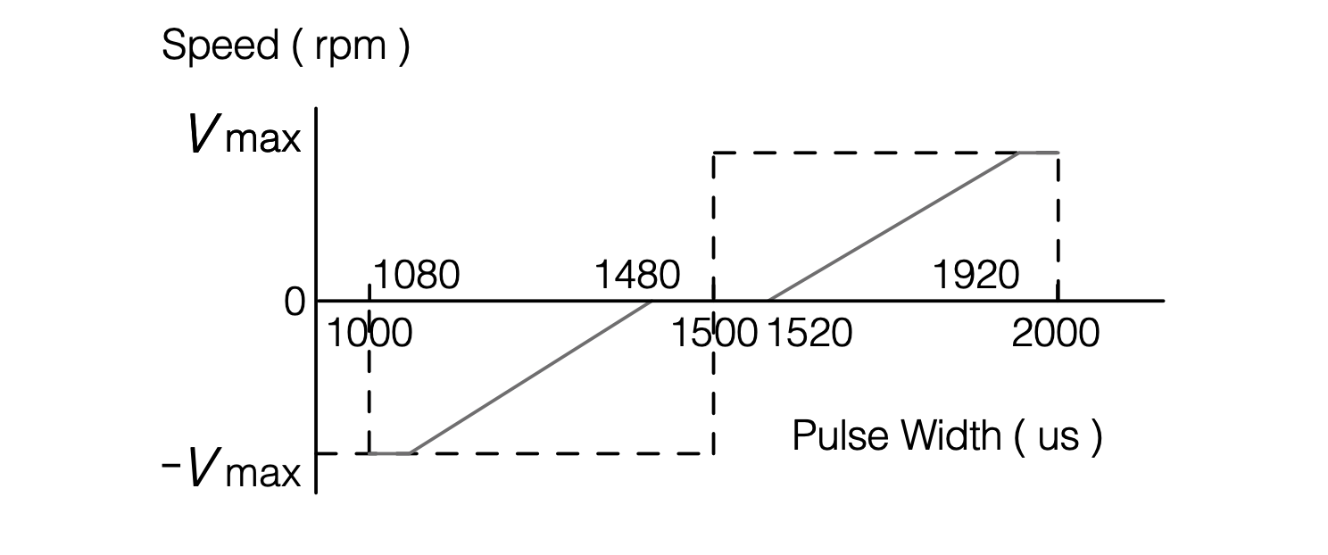
We need to keep the RM pwm at the resting on-time which is around 1465~1500(us), it may be different among different set of ESC and board (Please try the value between the range and find one suitable on your machine)
The frequency for controling rm is from 50Hz ~ 500Hz (personally i use 50Hz to do the testing)
If the LED light appears at blink 3 times that means the pwm signal you input isn't low enough, you can try other value, untill it blink at green light(and blink same number as it can id), and then it will stay at rest. Then you can turn the pwm value to other value to perform the work.
The on-time to the speed graph is shown at below.
How many motors for the wheelbase?
You can choose to use whatever kind of wheelbase(straight wheels or omni-wheels or mecanum wheels) Completely optional!!!
Straight wheels requires 2 or 4 motors, Omni-wheels requires 3 or more motors, Mecanum wheels need 4 motors
Omni-wheel robots and Mecanum wheel robots can walk in all direction without rotating which may make your game flow smoother by a lot.(Depends on the game flow, omni-wheel or Mecanum wheel may not be the best solution for all situations)
For more detail. Please refer to: Omni-wheel and Mecanum-Wheel
Last updated