Image Processing
NOTE: Image Processing in RDC 2023
For the Robot Design Contest 2023, you'll be doing the processing on your own computer and with OpenCV, meaning that you gain access to a lot of algorithms that come with the OpenCV library. In previous years, participants had to do image processing on the STM32 board, and had no access to OpenCV. This document was designed for those participants, who were expected to be able to write the algorithms by themselves after reading the document, and you will notice that a lot of the examples here are written in C. Despite this, I would still recommend taking the time to read through this document, as it covers a lot of the basic concepts about image processing, and explains the theory behind some of the more common image processing techniques (which OpenCV may also provide for you).
What is an image?
Before we start, it is crucial to understand what an image is. A representation of an image in computer is actually very similar to a spreadsheet. In fact, you can view a image with a spreadsheet application. Take a look at this image made in a spreadsheet for example. 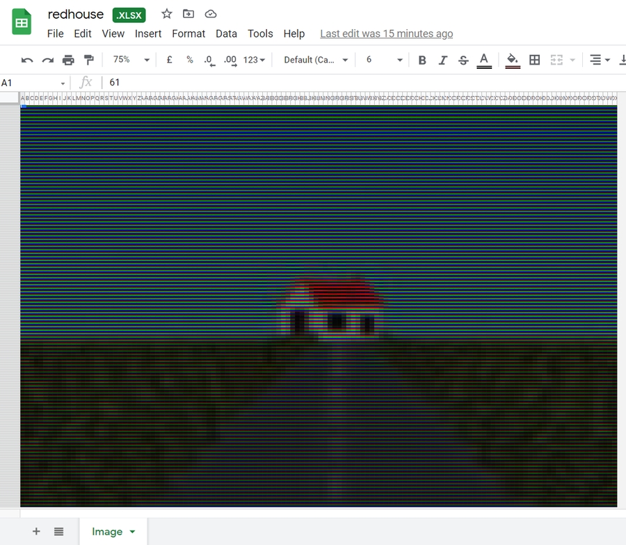
You might be wondering how this is possible. To answer your question, we need to zoom in to take a closer look.
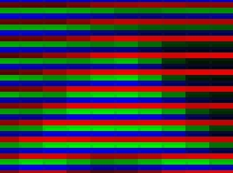
We can see that each cell is either red, green or blue. By using different brightness of the three colors, we can create an illusion that there are a lot of different colors.
To represent an image digitally, we need to store these cells, which are called pixels. Each pixel consist of the brightness value of the red, green and blue colors. These values in computers or robots are stored in a 2D array. You may have direct access to this array or may only be given a pointer. Note that the coordinate system of an image in computing is different from the coordinate system normally used in mathematics. The origin (0, 0) is on the top-left corner of the image.
Computer vision is one of the major perception systems in the robotics field. The robot receives image or video data from the camera module and stores it in the RAM.
Here is a camera module.

Before Image Processing
Since the camera image is stored in pixels in a 2D array, it is important to know the concept and implementations of arrays.
Here is a 2D array with width 5 and height 3:
[1][0]
[1][1]
[1][2]
[1][3]
[1][4]
[2][0]
[2][1]
[2][2]
[2][3]
[2][4]
The following demonstrates the typical way to print and manipulate 2D arrays:
Output
1. Image Type (Colored, Grayscale or Black&White)
Although a color mode setting may not exist in the emulator's camera, color modes are still worth learning. It is very important for real-life situations since it will affect the quality of the image you obtain.
Colored
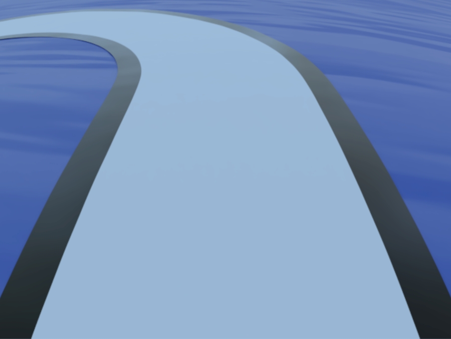
Please note that the images are rendered instead of taking in reality, so the image shown here may not fully represent the real image that you will be getting.
RGB565
If we want to have colored pictures, we also need information about the color. The color depth defines how many bits are used to represent a color. The more bits (information), the more colors we can display. There are different ways to represent a color but virtually all displays use RGB, where a color is represented by its Red, Green, and Blue components.
RGB565 requires only 16 (5+6+5) bits (i.e. 2 bytes) and is commonly used with embedded screens. Each pixel occupies 2 bytes, the bits are split into 3 groups to represent RGB respectively. The value stored in each group is just the intensity of that color.
R: Occupies 5 bits, so its value ranges from 00000 to 11111.
G: Occupies 6 bits, so its value ranges from 000000 to 111111.
B: Occupies 5 bits, so its value ranges from 00000 to 11111.
We concatenate the 3 values in the order R, G, B. So if R=11011, G=110010 and B=11010, then the final RGB565 value is 1101111001011010.
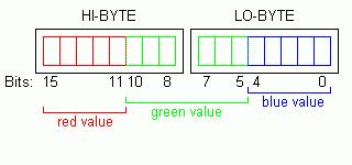
Note that the Green component has 6 bits, not because it needs higher values but because it needs higher resolution (see RGB 565 - Why 6 Bits for Green Color).
Grayscale
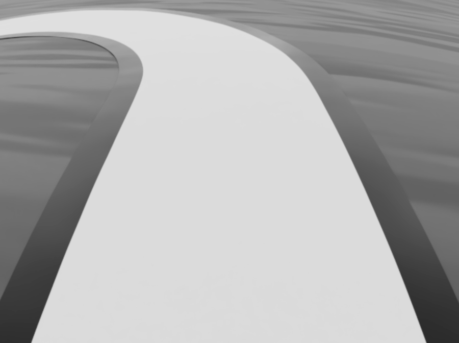
A grayscale image is essentially an image that only carries intensity information. Each pixel is just represented by a number that ranges from 0% (Total absence of light/ black) to 100% (Total presence of light/ white). Any fraction between is what we called 'gray'.
Note that if the RGB values in a colored image pixel are equal, there would be no color information. Therefore, we can also convert RGB565 images to grayscale images.
Average Method
Firstly, get the individual RGB components through bitwise operations.
Then, take the average value of the red, green and blue values to generate a grayscale value.
However, human eyes are more sensitive to green than other colors, averaging the three colors would generate an output that is less close to the original image under human perception.
Luminosity Method
Therefore, we combine the red, green and blue values with weights to generate a grayscale value.
A common ratio (weight) is R: 0.2989, G: 0.5870, B: 0.1140.
Try it yourself.
Pros and Cons of Using Different Image Type
Colored: (colors are stored as RGB in the MCU)
Pros: Contains a lot of details
Cons: Hard to control
Grayscale: (range from 0 ~ 255, where black = 0 and white = 255) Recommended
Pros: Relatively easier to control, able to use gradient to differentiate features
Cons: -
Black&White: (represented by 1 and 0, which black = 1 and white = 0)
Pros: Easiest to control
Cons: Hard to adjust thresholding for the image, has minimal information
These pros and cons are just a means to guide you. However, these rules aren't set in stone. It is general that for image processing, we would usually choose grayscale or black&white images to analyze as they provide adequate information in order to handle the dynamics of the car. The use of colored images may provide more information but it is up to you to determine if the extra information available is of any substantial benefit.
Black-and-White

A black-and-white image is an image that just contains either black (0) or white (1) in any pixels.
Setting a simple threshold for the grayscale image can generate a black-and-white image.
2. Brightness & Intensity
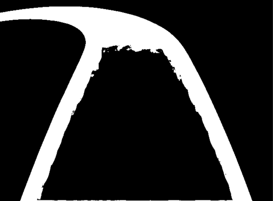
Apart from color choices, the brightness and the intensity of the image captured also affect the quality of the image you obtain, which in turn affect the ability to extract good data from it.
Low Intensity
Medium Intensity

High Intensity
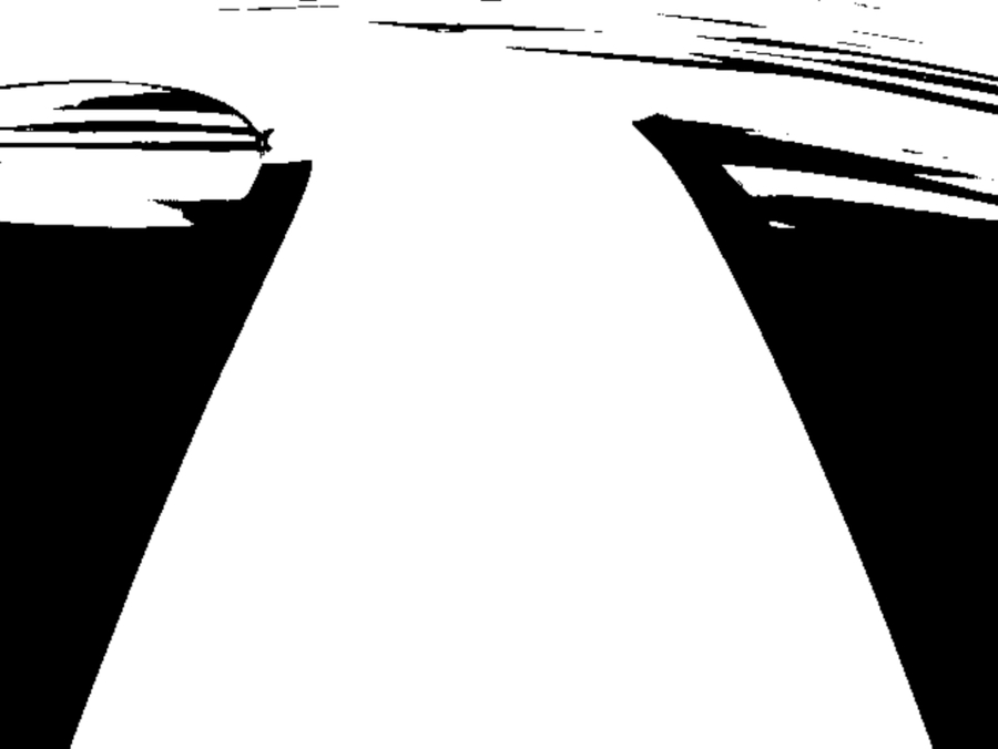
If you do not find the proper intensity, your image might contain noise that would deter you from processing the information accurately. It is important that your program is able to adjust the brightness and intensity based on different lighting conditions as it is against the rules to flash your program during the competition.
Here is a guideline if you want to write code to adjust the brightness and intensity of the image:
https://pippin.gimp.org/image-processing/chap_point.html
Convolution of image
Introduce to Kernel
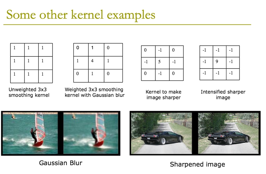
A kernel is a square matrix that specifies spatial weights of various pixels in an image. Different image processing contexts may use different kernels.
Convolution Process
Convolution of a matrix involves laying a matrix over another and then calculating the weighted sum of all pixel values. The example below uses a 3x3 kernel for convolution. If the input image is a mxn array, then the output array would be (m-2)x(n-2).
$105*(0)+102*(-1)+100*(0)+103*(-1)... = 89$
More examples:

Try it yourself: https://setosa.io/ev/image-kernels/
The weighting of each pixel entry is intuitive. For example a sharpening filter, we want to emphasize the center pixel and increase the color difference of it with the ones surrounding it. We would create a kernel like this:
0
-1
0
-1
5
-1
0
-1
0
To further intensify the sharpening effect:
-1
-1
-1
-1
9
-1
-1
-1
-1
Note that the sum of weighting is 1.
Application of Convolution - Reducing Noise
Usually the image generated by a camera might contain noise and will have to be filtered/ smoothened to prevent it from affecting the image analysis.
There are mainly two types of noise: salt-and-pepper noise and Gaussian noise.
Salt-and-Pepper Noise - Median Filter
Salt-and-pepper noise is a form of noise sometimes seen on images. It is also known as impulse noise. This noise can be caused by sharp and sudden disturbances in the image signal. It presents itself as sparsely occurring white and black pixels.

For salt-and-pepper noise, we can use a median filter.

Use of a median filter to improve an image severely corrupted by defective pixels.
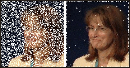
Example Code:
What if the image is too noisy and much information is missing?

A larger kernel size can be used, it smooths out the image better. However, a large kernel means the sharpness of the image is lost.
Gaussian Noise - Gaussian Filter
Gaussian noise is statistical noise having a probability density function equal to that of the normal distribution, which is also known as the Gaussian distribution. In other words, the values that the noise can take on are Gaussian-distributed.


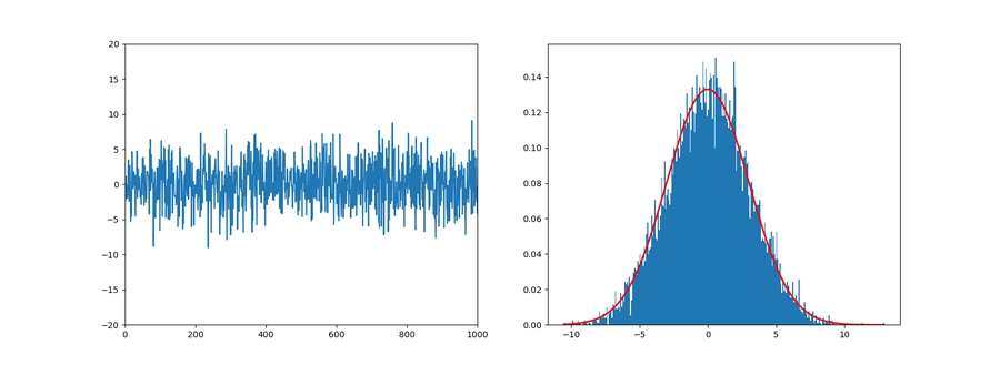
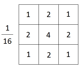
For Gaussian noise, we can use a Gaussian filter kernel.
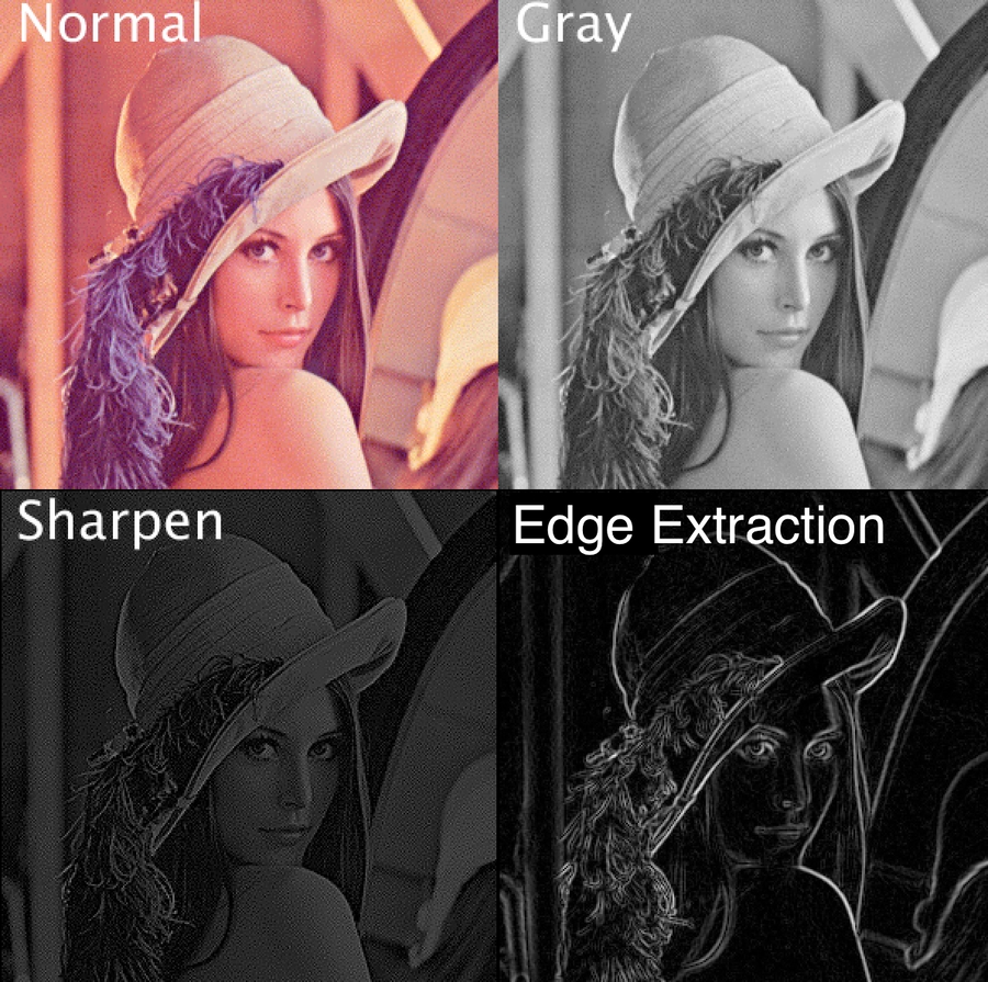
Application for Convolution - Feature Detection
Here are some images that have gone through the convolution.
Edge Detection - Sobel Filter
The Sobel filter emphasizes edges of an image.

Before:

After:
Why it works
Take a look at gx kernel first.
-1
0
1
-2
0
2
-1
0
1
If this kernel is place onto an area with no edge. It means that all the pixels in the area is about the same. Let's assume all the pixel have a value of C. The new value for the center pixel will be (-1C + 1C - 2C + 2C -1C + 1C = 0). The pixel will be black if all the pixels in the area are similar. The only place that the result pixel will be white is when the left and right side of pixels are very different (an edge).
The same can also be apply to gy. Finally, we can use the Pythagorean theorem to get the overall value.
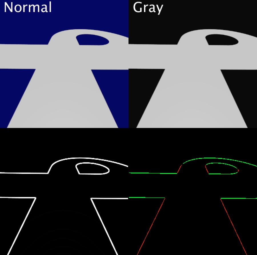
Convolutions can be extended to further detect other vital features of a track. Another key term to keep in mind is Gradient.
Points to remember:
Real life situations largely vary from digital replicated simulations. Application of algorithms should thus be geared to tackle the blemishes you would face.
Analyze features and algorithms from a mathematical and physical perspective.
Keep the program robust in order to tackle the worst cases possible.
Keep in mind the run time of your program during feature extraction.
Further Pondering
Applying convolution to the whole image is a processor-intensive task and might produce a large amount of unnecessary information. How can we only extract the information needed?
Or even better, only produce the information needed? (This will be crucial in our application.)
Last updated